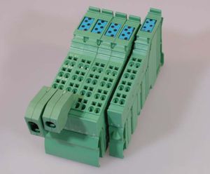
LOCON 200 (English)
Inhaltsverzeichnis
Configuration
By factory setting all LOCON 200 cam controls are configured as follows:
- Outputs: 16
- Encoder Type: SSI Singleturn
- Real Encoder resolution: 4096
- Virtual Encoder resolution: 4096
- Idle time: Bitwise
This configuration set by default may be changed by using TERM 6 or the software WINLOC 32.
Programming
LOCON 200 can be programmed by TERM 6 or TERM 24 or the software WINLOC 32. The PROFIBUS-Version can be programmed also via PROFIBUS.
Device versions
LOCON 200
LOCON 200 features a serial RS232-interface and a RS485-(DICNET) interface, the needed setting is made through the corresponding rotary coding switches High und Low, located at the bottom side of the device.
| High | Low | Meaning |
|---|---|---|
| D | DICNET-Adress | DICNET-Operation, Bus Termination inactive |
| E | DICNET-Adress | DICNET-Operation, Bus Termination active |
| F | F | RS232-Operation |
Only the DICNET-Addresses 0 ... 15 (decimal) are supported (right rotary coding switch Low = DICNET-Address). Examples:
| High | Low | Meaning |
|---|---|---|
| D | 3 | bus termination inactive, DICNET-Address 3 |
| E | C | bus termination active, DICNET-Address 12 |
'Note: The setting via the rotary coding switches is done in hexadecimal.
LOCON 200-PB (PROFIBUS)
LOCON 200-PB (PROFIBUS) is always PROFIBUS-Slave and features a serial RS232-interface and a PROFIBUS-Interface, instead of the RS485-(DICNET) Interface, the needed setting is made through the corresponding rotary coding switches High und Low, located at the bottom side of the device.
| High | Low | Meaning |
|---|---|---|
| 0 | 0 | PROFIBUS-operation, external address assignment |
| 0 | 1 | PROFIBUS-operation, Adress 1 |
| … | ||
| 7 | D | PROFIBUS-operation, Adress 125 |
| 7 | E | PROFIBUS-operation, external address assignment |
| F | F | RS232-operation |
Note: The setting via the rotary coding switches is done in hexadecimal.
In LOCON 200-PB two modes are selectable through WINLOC32 via the PROFIBUS-Interface.
- S7-Modus (ex-works condition): For an operation at a Simatic S7 and for use of the Data component simulator.
- Communication Profile Mode: For the Operation via the Communication Profile for Deutschmann cam controls.
The PROFIBUS-Address (Slave-ID) is set on 126 (decimal) in the factory setting. If the rotary coding switch is on position "00" und "7E" then any desired address can be assigned either through WINLOC32 or the PROFIBUS-Master. The GSD-file (L200.GSD) and a S7-example project are available for download on our homepage. Further information regarding LOCON 200-PB can be found in the manual Cam Controls with Fieldbus-Connection.
LOCON 200-MB (Modbus)
LOCON 200-MB (Modbus) is always a Modbus-RTU-Slave and is only available in the 2-core cable-version. LOCON 200-MB features a RS232-Standard-Interface as well as a RS232-(Modbus-RTU) Interface and a RS485-(Modbus-RTU) Interface, which can be changed by adjusting the rotary coding switch High located at the bottom side of the device.
| High | Low | Meaning |
|---|---|---|
| C | x | RS232-Modbus (X = ModbusSlave-ID) |
| D | x | RS485-Modbus without bus termination (x = Modbus-Slave-ID) |
| E | x | RS485-Modbus with activated bus termination (x = Modbus-Slave-ID) |
| F | x | RS232-Standard Interface |
Note: Only Modbus-Addresses 1 ... 15 (decimal) are supported (right rotary coding switch Low = ID). The Broadcast address 0 is not supported. The Setting via the rotary coding switch is done in hexadecimal.
The following Modbus-RTU-commands are supported by the device:
| command | meaning |
|---|---|
| 03 | (0x03) Read Holding Registers |
| 16 | (0x10) Preset Multiple Regs |
The transmission baud rate is 19200 Baud; No Parity. Further information regarding LOCON 200-MB can be found in chapter LOCON 200 with Modbus of the Manual for LOCON 200.
LOCON 200-Out I/O8 (extension module)
LOCON 200-Out I/O8 is an extension module and contains 8 I/Os. With this extension module the basic device LOCON 200 resp. (-PB)/(-MB) can be expanded (depending on the version) by 8 I/Os step-by-step to a maximum configuration level of 144 I/Os (incl. the 16 I/Os of LOCON 200 resp. (-PB)/(-MB)). LOCON 200-Out I/O8 contains an own processor. Therefore, the switching accuracy (cycle time) is independent of the LOCON 200(-PB)/(-MB) Basic module.
NT Module for LOCON 200-Out I/O8
The NT module for LOCON 200-Out I/O8 is a power supply that must be used for a configuration level step of more than 8 LOCON 200-Out I/O8 expansion modules. The NT module must be inserted immediately after the LOCON 200 basic unit. Nothing can be connected to the NT module itself. The voltage supply of the NT module takes place via the 24V/DC of the LOCON 200 basic unit. The voltage supply of the then following LOCON 200-Out I/O8 expansion modules is adopted by the NT module
Weblinks
- Manual for LOCON 200 (PDF-file)
- GSD-file for LOCON 200-PB
- S7-example project (ZIP-file)
- Manual Communication profile for Deutschmann cam controls (PDF-file)
- Manual Cam controls with fieldbus connection (PDF-file)
