Operating TERM 5, TERM 6, LOCON 16, LOCON 17
Inhaltsverzeichnis
Configuration
The here described configuration is only valid for cam controls LOCON 90, LOCON 100, LOCON 200, ROTARNOCK 80 and ROTARNOCK 100, which is done by TERM 6. LOCON 16 and LOCON 17 can only be configured by factory.
Reading and changing cam control parameters
All cam control parameters that can be reached via the communication profile with GET/SET-PARAMETER can be read and changed via a “menu point“ that is integrated in TERM 6.
Procedure:
- Starting from the main menu the keys + und - are pressed long for the same time period.
- Thereupon the function LED shines and a 1 (current parameter number) appears on the very right side of the TERM 6 display.
- Now this number can by changed by the keys + or - corresponding to the wanted parameter.
- Please see parameter table in the corresponding manual. Change of virtual encoder resolution
For instance please find here the change of the virtual encoder resolution.
- If the virtual encoder resolution is to be read/changed, please select (see parameter table in the manual communication profile) the corresponding parameter number 19 (corresponds 13H = PNR_SCALED_ENCODER_RES).
- Confirm with key Enter and the virtual encoder resolution of the connected cam control is displayed (e.g. 4096).
- If you want to change this value, please press the key Enter again long , until the Prog.Mode LED and the Function LED starts to flash.
- Now the value cany be changed with the keys + or - (e.g. 1000).
- By pressing again the key Enter the new value is loaded into the cam control.
- The value is rejected by pressing the key Esc.
Note The following error messages may appear in case of incorrect use during configuration:
- E34: change of the parameter not allowed
- E36: parameter dos not exist
- E37: Programming of an angle-time-cam larger than Output 16 (Output 8 only ROTARNOCK 80)
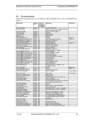
The parameter table can be found in the manuals of LOCON 90, LOCON 100, LOCON 200, ROTARNOCK 80 und ROTARNOCK 100. Here for example the parameter table of the manual ROTARNOCK 100.
Programming
Please find here an example how to program via the 4-key control panel in program 1, output 1 a cam from 100 to 200.
Procedure:
- By pressing the key Mode/Esc you can go to the program selection.
- With the keys + und - you can choose the wanted program (e.g. Program 1). Please confirm by pressing Enter.
- Thereupon you can select by pressing the keys + and - the wanted output (e.g. output 1). This output has to be confirmed by pressing the key Enter.
- Please press again the key Enter long until Prog. Mode LED and On LED start flashing.
- By using the keys + und - the switch-on-point can be programmed now (e.g. 100). Please confirm by pressing the key Enter.
- Now start flashing Prog. Mode LED and Off LED. By using the keys + and - the switch-off-point can be programmed now (z.B. 200). Again please confirm by pressing the key Enter.
- By pressing the key Mode/Esc you can leave the programming of the output resp. the otput itself and the selected program ( in this order).
A short manual regarding the programming is to be found in the manuals of LOCON 7, LOCON 9, LOCON 16, LOCON 17, LOCON 90, LOCON 100, LOCON 200, ROTARNOCK 1, ROTARNOCK 2, ROTARNOCK 3, ROTARNOCK 4, ROTARNOCK 80 und ROTARNOCK 100. Her as an example the short manual-programming for ROTARNOCK 100, originating from the manual of ROTARNOCK 100.
Program Change
Please find here an example how to change from program 0 to program 1 via the 4-key control panel.
- By pressing the key Mode/Esc you will reach the program selection. The active program is displayed (e.g. „P 0“ for program 0).
- By pressing the keys + and - you may select the desired program (e.g. „P 1“ for program 1).
- In order to activate the selected program, you have to press the key Enter for a longer time. In the display will appear PG CHG (Programm Changed).
- Thereafter please press the key Enter again for a longer time, only then the selected program is the active program.
Initialisation
Zero-point offset
Example: Your plant is mechanically already in position 0 . The new encoder is only to be set in the same position with a lot of work and effort. Via the 4 keys of the control panel the zero-point offset maybe handled in an easy way in a few steps without positioning the encoder with an effort.
Please find here a description how to program a zero-point offset.The actual encoder position (e.g.315) is not of importance.
Procedure:
- Please press long the key - until the Zero LED lights. The value displayed is changing from the actual encoder position (z.B. 315) to position 0.
- Please press now long the key Enter until Prog.Mode LED and Zero LED are flashing.
- Now you can program the desired encoder position by using the keys + and - (e.g. 0).
- Please confirm this value by pressing the key Enter , then the programmed value is stored in the cam control.
- The display shows now the acutal encoder position 0.
Note: This example is valid only for a cam control where no zero-Point offset is yet programmed.
Inverting the rotational direction of the absolute encoder
By factory setting all cam controls have a rotational direction clockwise.
Please find here a description how to program the inversion of the rotational direction.
Procedure:
- The key + has to be pressed long until Prog.Mode LED, Zero LED and Function LED are flashing. Now the display shows 0000.
- Now the inversion of the rotational direction can be done by pressing the key -, clockwise (0000) and anti-clockwise (0001).
- This change is confirmed by pressing the key Enter.
- By using the key ESC you return to the normal mode.
- Done.
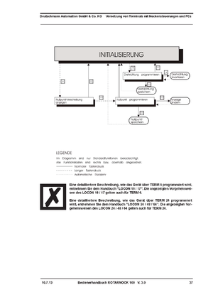
A short manual regarding the initialisation can be found in the manuals of LOCON 7, LOCON 9, LOCON 16, LOCON 17, LOCON 90, LOCON 100, LOCON 200, ROTARNOCK 1, ROTARNOCK 2, ROTARNOCK 3, ROTARNOCK 4, ROTARNOCK 80 und ROTARNOCK 100. Please find here as an example the short manual for initalisation originating from the ROTARNOCK 100 manual.
Interfaces
Available interfaces All devices are featuring a RS232 and a RS485 (DICNET) interface. By factory setting it is always set to RS485 (DICNET) interface. The interface can be switched manually. At the bottom site of the device is to be found a sticker with the imprint Interface. Under this sticker a microswitch is to be found to change the interface as desired.
Weblinks
- Manual for LOCON 16, LOCON 17 und TERM 6 (PDF-file)
- Manual for TERM 5 (PDF-file)


