Frequently asked questions Fieldbus- and Industrial-Ethernet-Devices
Inhaltsverzeichnis
- 1 Electronic cam controls
- 2 UNIGATE
- 2.1 I encountered problems with the RS232 connection between UNIGATE and PC. What can I do when WINGATE says "no Gateway found"?
- 2.2 Is Deutschmann providing test devices for testing?
- 2.3 How do I set the UNIGATE into the configuration mode (Configmode)?
- 2.4 What do I have to consider when I switch to UNIGATE CL from UNIGATE SC?
- 2.5 Does the UNIGATE IC support SPI?
- 2.6 How can I connect two networks(PROFIBUS / PROFINET)?
- 2.7 Fieldbus
- 2.7.1 CANopen
- 2.7.2 DeviceNet
- 2.7.3 EtherNet/IP
- 2.7.3.1 How do I switch to EtherNet/IP 2Port?
- 2.7.3.2 Why does the function ReadNewObjectDataEIP show a change of input data, altough all of the data is identical?
- 2.7.3.3 Can I only transfer an even number of bytes with an EtherNet/IP device?
- 2.7.3.4 Can a power supply separation be avoided through a script adaptation in a UNIGATE EtherNet/IP with firmware 4.0?
- 2.7.4 Fast Ethernet
- 2.7.5 PROFIBUS
- 2.7.6 PROFINET
- 2.8 Baureihe
- 2.9 PROTOCOL DEVELOPER
- 2.10 WINGATE
Electronic cam controls
External wiring
How is the modification from LOCON32-HC or LOCON32-PM to LOCON24 carried out?
Introductorily we like to point out that this description refers to a LOCON32-HC, that is/was configured "absolute parallel 360" as encoder type. Consequently the LOCON24 also has to contain this "O360" in the article text.
| LOCON 24 | Signal | LOCON 32-HC | LOCON 32-PM |
|---|---|---|---|
| X1 PIN 1 | OUT 1 | X10 PIN 2 | X1 PIN 1 |
| X1 PIN 2 | OUT 2 | X10 PIN 1 | X1 PIN 2 |
| X1 PIN 3 | OUT 3 | X10 PIN 4 | X1 PIN 3 |
| X1 PIN 4 | OUT 4 | X10 PIN 3 | X1 PIN 4 |
| X1 PIN 5 | OUT 5 | X10 PIN 6 | X1 PIN 5 |
| X1 PIN 6 | OUT 6 | X10 PIN 5 | X1 PIN 6 |
| X1 PIN 7 | OUT 7 | X10 PIN 8 | X1 PIN 7 |
| X1 PIN 8 | OUT 8 | X10 PIN 7 | X1 PIN 8 |
| X1 PIN 9 | OUT 9 | X10 PIN 10 | X1 PIN 9 |
... more
Modelle
What has to be considered when using a LOCON200 in connection with TERM24?
If a (discontinued) device is supposed to be replaced by a LOCON200 and in case a TERM24 is used in the assembly, then the TERM24's Firmware must be updated at any rate. For the update the device has to be sent back to us.
TN65 - ROTARNOCK - what is it?
It is the same unit. ROTARNOCK describes the product line and TN65 is the specific type or the article description.
Example: ROTARNOCK 100 - describes the ROTARNOCK-family "100". The exact article description would be: TN65-4096-100-I232-E-N - there are different versions though. | | | | | | | | | | | -> Hardware option = here zero-point LED | | | | -> Shaft diameter = always 10mm | | | -> Type of idle time and interface = here bitwise and RS232 | | -> Device family = ROTARNOCK 100 | -> Resolution per revolution (real) = At R100 configurable as desired -> Identification for ROTARNOCK In case of questions concerning the order designation or an alternative device for a unit, whose production is discontinued, our distribution partners are pleased to be at your assistance.
How do you change the Profibus Ident Number?
To change the Profibus Ident Number from 3606H to 3231 the ROTARNOCK100-PB has to be connected with the PC via a serial communication (RS232). For the serial communication the following pin assignemt is valid here:
PC PIN2 (Rx) <-> ROTARNOCK 25pin D-Sub PIN17 (Tx RED) PC PIN3 (Tx) <-> ROTARNOCK 25pin D-Sub PIN18 (Rx RED) PC PIN5 (GND) <-> ROTARNOCK 25pin D-Sub PIN25 (GND)
A corresponding programming cable (including plug-in power supply) is to be ordered with the article number V3467.
The software WINLOC32 has to be installed on th PC. The interface parameters are entered in "Extras" -> "Options" -> "Port".
If the ROTARNOCK is now supplied with voltage a window opens automatically and the device brings its start-up message, e. g.: R100-48-O4096-PB(126)-232 V3.54 Ok Now place in WINLOC32 the cursor behind the last character (through a "left click") and press "n" while keeping the keys "STRG/CTRL" pressed. The following confirmation prompt appears: Ident-Nr=3606H, change to 3231H (Y/N)? N This query has to be confirmed with "y" within 3 seconds and the following confirmation appears: New Ident-Nr = 3231H After a re-start the device uses the new Ident Number and it can be put into operation.
The same way the Ident Number can also be changed back from 3231H to 3606H.
How do I replace a ROTARNOCK1/2/3/4 by a ROTARNOCK100?
There are two ways to carry out the exchange.
1. Exchange with the convenient programming software for cam controls WINLOC32 (recommended procedure): Read out (File->Upload) the ROTARNOCK that is to be replaced with the software WINLOC32 and store (File->Save) it on the hard disk or open an existing configuration file. Change from the current view to the view device configuration by clicking on the lettering Configuration on the left side of the configuration file. Activate all selection buttons on the right side. Please write down the following values provided that they are indicated: Encoder resolution, ITC (=idle time compensation) Type, Display factor, ITC Function, Turn Direction, Run-Control and Zero shift. Important: Please write down the indicated position during downtime (best in the basic position if possible) before removing the old device! Connect the ROTARNOCK100 now and carry out an upload or open an existing configuration file. Both, the ROTARNOCK 100 as well as the available configuration file should be unused, otherwise a configuration is not possible. How to set the ROTARNOK100 back in default mode can be found here. Change the current view by clicking on the lettering Configuration. Carry out the configuration now by clicking on Device Reconfiguration on the window's right side. Enter the value for the Virtual Resolution here and select the ITC Type and confirm it with OK. Change to the configuration view again and activate all selection buttons on the right side. Transfer those values from the old ROTARNOCK, you have written down before, to the new device. Provided that you have written down the value RunControl=yes, you have to set the Run-Control-output to I/O16 and the Run-Control-type to blink! Important advice: Depending on the application's construction there are different safety mechanisms. If you continue to transfer the cam values now and to download the complete program into the ROTARNOCK the outputs are directly active in dependence on the position and the cam values. This might lead to an unintentional "failure/scrap" of the application. We recommend to carry out the zero adjustment first before the cams are being transmitted to the device. Load the newly generated configuration in the ROTARNOCK100 through Download. Install the ROTARNOCK100 now and change the zero shift offset's value, until (or change the axis mechanically) the currently displayed position is the same as the one you have written down before. There are many different possibilities to carry out the zero adjustment. Sometimes they are also combined. Therefore please carry out an update again after the adjustment. In WINLOC32 the cam values, idle times and output names are transmitted from the old configuration file to the new one through Extras -> Data transfer. This function is only available in the Comfort version of WINLOC32. We are pleased to help you transmitting the data also without the Comfort version. To do so, please send an e-mail with both configuration files to hotline@deutschmann.de. After the data has been transmitted and verified, the complete file can be saved now and loaded into the device. With it the exchange is completed.
2. Exchange with manual configuration and programming with TERM6 or TERM24 (with current Firmware): The following information on the ROTARNOCK that is to be exchanged should be available: Encoder resolution, type of idle time, turn direction, indicated position before removing the old device (best in the basic position) as well as all cam values and idle times. Advice: In case your old device features the option R - RunControl, then the device has to be configured with WINLOC32. Carry out the exchange. Set the (virtual) encoder resolution and the idle time accordingly via the terminal now. The procedure is described in the corresponding manual. After that the adaptation of the sense of rotation, if necessary, occurs and after that the adjustment of the zero point. The TERM is supposed to indicate the same position as before the exchange. Now you can start entering the cams and idle times and finally the application can be tested and be put into operation. Note: Even though this procedure sounds to be short and simple you have to proceed very carefully. To enter a lot of cams is much more time-consuming than the procedure with WINLOC32.
Software tools
Configuration- and programming-software for cam controls?
A configuration- and programming-software WINLOC32 is available for all Deutschmann cam controls (NS). The basic version of that software is available free of charge (in the download-area and on the support CD). This basic version already features extensive functions. The cam control can be read out, configured and programmed. Also these files can be stored. By means of a »key« available against charge the comfort functions will be activated (online function, comfortable copying and displacing of programs....). A license that was purchased once is valid for all existing and following versions of the program. Cam controls with RS232-interface can directly be connected with the PC's COM-interface (see corresponding instruction manual for the cable connection). The cam control's signal TxD has to be wired with the PC's signal Rx and vice versa. The GND has to be wired as well. For cam controls with DICNET(485)-interface a DICADAP3 has to be used in order to connect the device with the PC. At the same time the DIC+ and DIC- wires are interconnected.
How and where do I enter the WINLOC32 comfort version license key?
First of all start WINLOC32. In the menu line "Extras" -> select "Options". A window opens. If necessary please change to the register "License". Now enter the license key you received from us. Note: When you start to enter the key the line "licence code valid" is displayed in red. If the key is entered correctly, then it turns to green. Each entered character is displayed as "*". A license that have been purchased once can be used for all follow-up versions. A WINLOC16 license also works with WINLOC32.
UNIGATE
I encountered problems with the RS232 connection between UNIGATE and PC. What can I do when WINGATE says "no Gateway found"?
If the UNIGATE sends a message, but WINGATE says "no Gateway found", the Rx line is not properly connected to the UNIGATE. Check the line with a meter (DVM): between GND and Rx = 7 V, as well as GND and Tx = 7 V. The 7 V may vary between 6 and 9 V, but have to be equal on one unit. If one of the two connections is 0 V, Rx and Tx are switched or connected incorrectly.
Is Deutschmann providing test devices for testing?
We have the longstanding rule that if a customer buys a device, he has a general right of return of 30 days.
How do I set the UNIGATE into the configuration mode (Configmode)?
For all Deutschmann UNIGATE devices (except UNIGATE CL & UNIGATE IC) the interface switch has to be set to "RS232" and the two rotary switches S4+S5 must be set to "FF" on the serial side. For the UNIGATE CL the RS232 interface is automatically active throught the switch positions of S4+S5 with "FF". If you use the UNIGATE IC the basis board of the J17.
After a reboot of the device, the device sends the switch-on message in a terminal program (eg WINGATE) via the application interface (NOT DEBUG) Nach einem Neustart des Gerätes bringt das Gerät über die Applikationsschnittstelle (NICHT DEBUG!) die Einschaltmeldung in einem Terminalprogramm (z.B. WINGATE):
IC-PB-SC PV5.9B[30] (c)dA Script(2k)="Leer" Author="Deutschmann Automation GmbH" Version="1.0" Date=21.08.2001 SN=xxxxxxxx ID=1 Configmode...
Now you know that the unit is in configuration mode.
Practice Tip: With UNIGATE CL, RS and SC the configuration mode is visually indicated by the RS-"State" LED flashing red.
What do I have to consider when I switch to UNIGATE CL from UNIGATE SC?
There is one significant difference between a SC and a CL: the SC devices have a hardware switch "232 <-> 485", which does not exist on a CL. The CL on the other hand has all interfaces (232/485/422) on board. You still have to consider that if you don't run the RS, you have to run an extra Set(RS_Type,[?]) command. In the PROFIBUS version there is also the difference of the ID number. The UNIGATE CL-DP needs the GSD file UGIC3218.gsd.
Does the UNIGATE IC support SPI?
Yes, the UNIGATE IC supoorts SPI. (Up-to-date UNIGATE IC Pinout-List in XLS Format) Pin 3...7 are for the SPI Master (SPI slave on request only) We support 2 different SPI functions: SPI Slow and SPI normal. For SPI Slow you can use the example "example_SPI_slow.dss". For SPI normal, the example "example_SPI.dss" is available (not available for FIDO based Hardware: PROFINET, EtherNet/IP). For FIDO based hardware you can make use of the example "example_SPI_Pinout_Real.dss". I2C is currently not supported.
How can I connect two networks(PROFIBUS / PROFINET)?
To establish a connection between two networks (PROFIBUS / PROFINET) you can use a UNIGATE CX. In the delivery state the default setting makes for a transparent data exchange between the two fieldbus systems. You have to keep in mind that the UNIGATE CX works as a slave, which means the Master must take over the communication in every network.
Fieldbus
CANopen
UNIGATE CO (M)-PROFIBUS DP
I encountered problems after downloading the existing/old GWC-file into my new device. Can you list the various steps?
- Open the desired GWC file with the configuration tool WINGATE.
- Then start the new device and perform the download
- Now perform an Upload from the device
- The parameter "CAN baud rate" is now at 125k.
- If the baudrate is set using the DIP switch you have to change the parameter. Therefor the parameter has to be selected. By double-clicking a window opens in which the "DIP switch" has to be selected.
- Afterwards perform another download
- Save the change, respectively the "new" GWC file
In a further download of these "new" GWC files into a new device the "CAN baud rate" parameter is now set accordingly and doesn't have to be changed again.
How do I replace CANopen (Master) - PROFIBUS DP (Slave)?
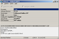
- Start WINGATE:
- Connect the RS232 from PC to UNIGATE (3 wire, 3 pin connector)
- Connect power supply
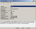
- Upload file
- Save file
- Disconnect the old UNIGATE
- Connect the new UNIGATE (see Step 1)
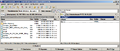
- Afterwards click "File - Download" (write to device)
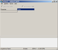
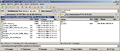
1. Start WINGATE
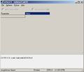
3. Connect power supply
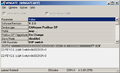
4. File upload
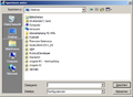
4. Save as
8. File-Download
.png)
_Versorgungsanschluss.png)
_File_upload.png)

_File_download_screen.png)
In WINGATE-File the Adresse 0x14 is set to 0
With the new Firmware V2.60 in WINGATE the config file has to be stored with the setting "baud rate: DIP Switch"
DeviceNet
How much power does the UNIGATE IC draw at the DeviceNet power supply 24 Volt connector, PIN 17?
The current consumption is max. 35mA.
EtherNet/IP
How do I switch to EtherNet/IP 2Port?
Explanation: Address Conflict Detection
Why does the function ReadNewObjectDataEIP show a change of input data, altough all of the data is identical?
In the cyclic data packets a counter value is also transmitted besides the payload. This counter can be incremented into every cycle by the SPS, or only if a change of payload occurs. The command ReadNewObjectDataEIP indicates a change if the counter value changes.
Can I only transfer an even number of bytes with an EtherNet/IP device?
No, as of firmware version 4.0 the number of transferredd bytes per cycle can also be odd (e.g. 7 byte Input, 3 byte Output).
Can a power supply separation be avoided through a script adaptation in a UNIGATE EtherNet/IP with firmware 4.0?
The UNIGATE has to be restarted after setting the IP address via "Set(FieldbusID,". Unfortunately, from a programm technology perspective there is no other way, since the IP address is already read from the EEROM area when booting, to start the Ethernet part of the Fieldbusstacks. Only if this part is started correctly our application begins (i.e. the script).
Fast Ethernet
Gibt es ein Beispiel für die Web-Server Funktionalitäten?
Ja, es gibt ein Beispiel, welches nach der Installation des PROTOCOL DEVELOPERS verfügbar ist.
- Start Sie das UNIGATE CL-FE im Konfigmode
- Gerät zurücksetzen (WINGATE - options - reset device)
- Speichern Sie das Script-Beispiel: Wingate – File – Write script ... :\Software\ProtocolDeveloper\Example\08 Bus specific\Fast Ethernet script.dcs
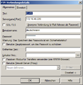
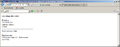
- Stellen Sie die IP-Adresse und die Subnetmaske ein (Vergessen Sie nicht die Datei herunterzuladen)
- Starten Sie das UNIGATE im Run mode (S4+5 nicht FF und nicht EE)
- Starten Sie einen FTP Client, wie Total Commander. Stellen Sie eine FTP Verbindung her. (Benutzername und Passwort: deutschmann)
- Verzeichnis: Flash
- Kopieren Sie die "index.html" zu CL-FE
- Starten Sie Ihren Browser und geben Sie die in WINGATE angelegte IP-Adresse an
- Wenn Sie die Seite aktualisieren (F5) sehen Sie dass sich der Zahlenwert erhöht.
- Und das war es auch schon!
4. IP-Adresse und Subnetmaske
6. FTP Client
7. Verzeichnis ändern
8. index.html kopieren
9. IP-Adresse im Browser
_Set_IP_Adress_set_subnet_mask.png)


Gibt es mittlerweile bei den CL Geräten mit RJ45 Buchse den Temperaturbereich bis -40°C?
Bei den CL haben wir keine Änderungen gemacht. Hier haben wir nur die Aussage des Herstellers, dass -40°C kein Problem sind, wenn bei diesen Temperaturen keine Steckverbindungen durchgeführt werden. Bei unserer Erweiterungskarte für CL und beim FC ist ein RJ45 für -40°C eingesetzt.
PROFIBUS
Wie kann ich das UNIGATE IC PROFIBUS DPV1 5V ohne 485 Treiber einsetzen und wie viel Strom kann der DC/DC Wandler auf der Feldbusseite leisten?
Deutschmann setzt einen 1W-DC/DC Wandler ein, der bei 5v 200mA versorgen kann. Von diesen 200mA benötigen wir auf der Platine ohne Treiber selbst deutlich weniger als 50mA, so dass für den Anwender 150mA verbleiben, die sicherlich ausreichend sind.
Slave ID ändern über SPS
ID wird im EEROM gespeichert.
var LBusState     : Long ;
var L0xE0         : Long ;         moveconst ( L0xE0, 0xE0);

BusStart ;
//Wait ( Bus_Active ) ;

:LoopBusState;
Get ( ReadBusState , LBusState ) ;
if LBusState less L0xE0 then :LoopBusState;   //!!! neu
PROFIBUS GSD Datei - Wie erstellt man eine andere Konfiguration?

It is also possible in some configuration tools, like Step 7, to use a “Universal Modul”, this is not mentioned in the GSD file. It seams this is a special feature. In this Modul, you can setup every size.
Slave ID über den Master setzen
Wird die Slave ID über einen Master gesetzt und dabei das MSB gesetzt („Slave Adresse kann nicht mehr verändert werden“), kann man das Flag nur durch ein „Reset Device“ mit WINGATE im Konfigmode zurückgesetzt werden. Achtung: dabei wird das EEROM neu initialisiert und das Script gelöscht.
PROFINET
PROFINET GSDML - Darf man die GSDML-Datei umbenennen?
Die GSDML-Datei darf nicht umbenannt werden. Der Dateiname der GSDML-Datei ist auch in der Datei selbst hinterlegt. Wird nun der Dateiname einfach umbenannt, bleibt der Ursprüngliche Dateiname in der Datei erhalten. Bei Verwendung dieser umbenannten GSDML-Datei, meldet das System, dass die eingefügte Datei nicht eingebunden werden kann, da diese nicht dem gültigen Format entspricht.
PROFINET Inbetriebnahme
PROFINET IO-Geräte - Adressen- und Namensvergabe

Wie kann ich Deutschmann PROFINET Geräte an eine S7 anschließen?
PDF Download in Deutsch/Englisch [2]
Script mit Stationsname

Es muss im Script ein BusStart erfolgen, dann wird der Name dem Stack übergeben im PROFINET Master angezeigt. Allerdings wird der Name nur temporär übergeben. D.h., wenn das UNIGATE im Konfigmode gestartet wird, wird der Name aus der Datei devname.txt genommen. Wird dann im PROFINET Master ein Name gesetzt ist dieser wirksam.