Frequently asked questions Fieldbus- and Industrial-Ethernet-Devices
Inhaltsverzeichnis
- 1 Fieldbus
- 1.1 CANopen
- 1.2 DeviceNet
- 1.3 EtherNet/IP
- 1.3.1 How to switch to EtherNet/IP 2Port?
- 1.3.2 My PLC cannot establish a connection to my EtherNet/IP device. What could be the reason?
- 1.3.3 Why does the function ReadNewObjectDataEIP show a change of input data, altough all of the data is identical?
- 1.3.4 Can I only transfer an even number of bytes with an EtherNet/IP device?
- 1.3.5 Can a power supply separation be avoided through a script adaptation in a UNIGATE EtherNet/IP with firmware 4.0?
- 1.4 Fast Ethernet
- 1.5 PROFIBUS
- 1.5.1 At commissioning a PROFIBUS-slave I do not see any input data when put and also it is not possible to send data to the device.
- 1.5.2 How to use the UNIGATE IC PROFIBUS DPV1 5V without driver 485 and how much current can the DC/DC converter provide on the fieldbus side?
- 1.5.3 Changing of the Slave ID via SPS
- 1.5.4 Which GSD-file is meant for my device?
- 1.5.5 GSD Datei - How to create a different configuration?
- 1.5.6 How to set the Slave ID via the Master?
- 1.5.7 How to realize the conversion from Fieldbus ↔ Modbus RTU (Master)?
- 1.6 PROFINET
- 2 Series
- 2.1 UNIGATE CL
- 2.1.1 Can I use my configuration file of the series UNIGATE RS for UNIGATE CL as well?
- 2.1.2 I want to download my UNIGATE SC-PB Script into the UNIGATE CL-PB. The PROFIBUS State LED remains red and/or the serial communication does not work.
- 2.1.3 How to configure the UNIGATE CL with WINGATE?
- 2.1.4 Can you deliver the Protocol Converter UNIGATE CL in a lacquered version?
- 2.2 UNIGATE IC
- 2.3 UNIGATE RS
- 2.1 UNIGATE CL
Fieldbus
CANopen
UNIGATE CO (M)-PROFIBUS DP
I encountered problems after downloading the existing/old GWC-file into my new device. Can you list the various steps?
- Open the desired GWC file with the configuration tool WINGATE.
- Then start the new device and perform the download
- Now perform an Upload from the device
- The parameter "CAN baud rate" is now at 125k.
- If the baudrate is set using the DIP switch you have to change the parameter. Therefor the parameter has to be selected. By double-clicking a window opens in which the "DIP switch" has to be selected.
- Afterwards perform another download
- Save the change, respectively the "new" GWC file
In a further download of these "new" GWC files into a new device the "CAN baud rate" parameter is now set accordingly and doesn't have to be changed again.
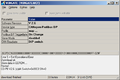
How to replace CANopen (Master) - PROFIBUS DP (Slave)?
- Start WINGATE:
- Connect the RS232 from PC to UNIGATE (3 wire, 3 pin connector)
- Connect power supply
- Upload file
- Save file
- Disconnect the old UNIGATE
- Connect the new UNIGATE (see Step 1)
- Afterwards click "File - Download" (write to device)
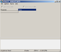
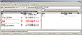
1. Start WINGATE
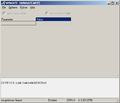
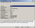
3. Connect power supply
4. File upload
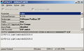
4. Save as
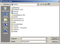
8. File-Download
.png)
_Versorgungsanschluss.png)
_File_upload.png)

_File_download_screen.png)
In WINGATE-File the Adresse 0x14 is set to 0
With the new Firmware V2.60 in WINGATE the config file has to be stored with the setting "baud rate: DIP Switch"
DeviceNet
How much power does the UNIGATE IC draw at the DeviceNet power supply 24 Volt connector, PIN 17?
The current consumption is max. 35mA.
EtherNet/IP
How to switch to EtherNet/IP 2Port?
You can find more about switching to EtherNet/IP 2 Port on the UNIGATE CL EtherNet/IP site: Changeover to 2-Port devices
My PLC cannot establish a connection to my EtherNet/IP device. What could be the reason?
Maybe you configured your PLC to use a Unicast connection.
If you are using the Rockwell software RSLogix 5000 you can check this in the UNIGATE's module properties dialogue. Please make sure the option "Use Unicast Connection over EtherNet/IP" on the connection tab is disabled.
Why does the function ReadNewObjectDataEIP show a change of input data, altough all of the data is identical?
In the cyclic data packets a counter value is also transmitted besides the payload. This counter can be incremented into every cycle by the SPS, or only if a change of payload occurs. The command ReadNewObjectDataEIP indicates a change if the counter value changes.
Can I only transfer an even number of bytes with an EtherNet/IP device?
No, as of firmware version 4.0 the number of transferredd bytes per cycle can also be odd (e.g. 7 byte Input, 3 byte Output).
Can a power supply separation be avoided through a script adaptation in a UNIGATE EtherNet/IP with firmware 4.0?
The UNIGATE has to be restarted after setting the IP address via "Set(FieldbusID,". Unfortunately, from a programm technology perspective there is no other way, since the IP address is already read from the EEROM area when booting to start the Ethernet part of the Fieldbusstacks. Only if this part is started correctly our application begins (i.e. the script).
Fast Ethernet
Is there an example of the web server functionality ?
Yes, there is an example, which is available after installing the PROTOCOL DEVELOPER.
- Start the UNIGATE CL-FE in configmode
- Reset device (WINGATE - options - reset device)
- Save the script example: Wingate – File – Write script ... :\Software\ProtocolDeveloper\Example\08 Bus specific\Fast Ethernet script.dcs
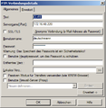
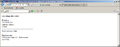
- Set the IP address and the subnet mask (Do not forget to download the file)
- Start the UNIGATE in Run mode (S4+5 not FF and not EE)
- Start a FTP Client, such as Total Commander. Establish a FTP connection. (Username and password: deutschmann)
- Directory: Flash
- Copy "index.html" to CL-FE
- Start your browser and enter the IP address you created in WINGATE
- If you refresh your browser (F5) you will see that the numerical value increased
- That's it!
4. IP address and subnet mask
6. FTP Client
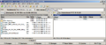
7. Change directory
8. Copy index.html
9. IP address in Browser
_Set_IP_Adress_set_subnet_mask.png)


Is the temperature range down to -40°C by now available for CL devices with RJ45 connectors?
We did not make changes to the CL. We only have the statement of the manufacturer that -40°C are no problem if there are no plug connections made at these temperatures. In our expansion card for CL and FC a RJ45 for -40°C is used.
PROFIBUS
At commissioning a PROFIBUS-slave I do not see any input data when put and also it is not possible to send data to the device.
For CPUs from the company Siemens only direct access up to 4 bytes is possible. Provided that useful data > 4 bytes are supposed to be read or written, then the access has to be made through the SFC14 (read) and SFC15 (write). Further information can be found in the projection software's help.
How to use the UNIGATE IC PROFIBUS DPV1 5V without driver 485 and how much current can the DC/DC converter provide on the fieldbus side?
Deutschmann uses 1W-DC/DC converter, which can be supplied at 5V with 200mA. On the board without driver we need much less than 50mA of these 200mA, which means 150mA remain for the user. These are certainly adequate.
Changing of the Slave ID via SPS
ID is stored in EEROM.
var LBusState     : Long ;
var L0xE0         : Long ;         moveconst ( L0xE0, 0xE0);

BusStart ;
//Wait ( Bus_Active ) ;

:LoopBusState;
Get ( ReadBusState , LBusState ) ;
if LBusState less L0xE0 then :LoopBusState;   //!!! neu
Which GSD-file is meant for my device?
We distinguish between 2 versions: DPV0 and DPV1. You can tell from the article description which device is in front of you. A »DP« stands for DPV0; a »DPV1« for itself. The UNIGATE IC-DPL and UNIGATE CL is a DPV1-device.
In the download-area of the respective device only that GSD-file, which is valid for the corresponding device only, is placed at your disposal for download.
A DPV1 slave is downwards compatible and it can also operate in the DPV0 mode. Nevertheless, the DPV1 GSD-file has to be used.
DPV0 slave → GSDfile »DAGW2079.GSD«
DPV1 slave → GSD-file »UGIC3218.GSD«
GSD Datei - How to create a different configuration?

It is also possible in some configuration tools, like Step 7, to use a “Universal Modul”, this is not mentioned in the GSD file. It seams this is a special feature. In this Modul, you can setup every size.
How to set the Slave ID via the Master?
If the Slave ID is set via a Master and the MSB is also set ("Slave address can not be changed anymore"), the flag can only be reset through a "Reset Device" in the configuration mode in WINGATE.
WARNING: With it the EEROM will be re-initialized and the script will be deleted.
How to realize the conversion from Fieldbus ↔ Modbus RTU (Master)?
This proceeding for a UNIGATE CL-PROFIBUS DPV1 is used as an example for all UNIGATEs and the supported Fieldbuses.
UNIGATE CL is supplied with a Universal Script that makes setting the "Modbus RTU (Master)" protocol very simple. A detailed description how to configure the device can be found here.
Note: In case you want to read out the same register several times, then the parameter "Data Exchange" should be adjusted to "On Trigger". In this case the UNIGATE expects the togglebyte in the Fieldbus Master's first byte.
Application:
The Fieldbus Master requests (read holding register = 03) the register "4567" with the length of 1 word from the Modbus Slave with the ID=2. The resulting inquiry from the Profibus-Master to the UNIGATE is:
02 03 45 67 00 01
(ID=2, read register=03, register=4567 and length in words high + low=0001)
The UNIGATE converts data to Modbus and adds the checksum (=xx):
02 03 4567 00 01 xx
The UNIGATE receives the following response from the Modbus Slave with the ID=2:
02 03 02 03 E8 xx
(ID=2, read register=03, length in byte =02, value of the register 4567=03E8 and checksum=xx)
The UNIGATE puts the Modbusslave's response on the Fieldbus:
02 03 02 03 E8
Consequently a complete inquiry from the Fieldbus Masters has been converted to Modbus and the Slave's response has been issued to the Fieldbus in turn.
The above proceeding describes the function of the UNIGATE RS, UNIGATE CL with Universal Script and configured Modbus-RTU(Master) protocol as well as our Script examples Modbus-RTU(Master).
There are also applications, in which the UNIGATE is supposed to read out a corresponding register or also the UNIGATE cyclically reads the same regsiter again and again through only 1 byte of the Fieldbus Master. With our UNIGATE SC, CL and IC this is possible without a problem. In these two cases the Script only has to be adapted to this requirement. Please use our Script examples for this.
PROFINET
How to connect Deutschmann PROFINET devices to a S7?
For a step-by-step instruction, please download the PDF [1].
How to evaluate a UNIGATE device with a PROFINET interface?
You can evaluate your PROFINET device (UNIGATE CL-Profinet, UNIGATE IC-Profinet, UNIGATE FC-Profinet) with our free PROFINET Module software. All you need is a Microsoft Windows computer with an Ethernet port. The PROFINET Module software is part of our Starter Kit software collection which can be obtained from the download section.
Why can't I assign a device name to my UNIGATE?
For PROFINET the device name is subject to a naming convention. For example, the use of capital letters is not allowed.
How to rename the GSDML file?
The GSDML file can not be renamed. The file name of the GSDML file is also stored in the file itself. If you now rename the file, the original file name is retained in the file. Using this renamed GSDML file, the system reports that the inserted file can not be included because it does not correspond to the valid format.
Script with station name

A BusStart has to be done in the script, then the name will be passed to the stack and appear in the PROFINET Master. However, the name is only given temporarily. Meaning, if the UNIGATE will be started in the config mode, the name will be taken from the file devname.txt. If a name is then set in the PROFINET Master it is effective from now on.
Series
UNIGATE CL
Can I use my configuration file of the series UNIGATE RS for UNIGATE CL as well?
We will be supplying the devices UNIGATE CL with a "UNIVERSAL" script (if it had not been handled that way so far). This script then acts as if it was a UNIGATE RS. That means that the UNIGATE CL can be parameterized via the configuration software WINGATE. An "old" UNIGATE RS configuration file is not compatible with that of the UNIGATE CL. If a UNIGATE RS is to be changed over to UNIGATE CL, then the UNIGATE CL must be read out once via WINGATE and the protocol settings have to be made. This configuration can then be stored in the usual manner and it can be used again for devices of the same type.
Note: If a "Reset Device" is carried out with a UNIGATE CL, then the "UNIVERSAL" script gets lost and it has to be loaded again.
I want to download my UNIGATE SC-PB Script into the UNIGATE CL-PB. The PROFIBUS State LED remains red and/or the serial communication does not work.
This "phenomenon" has two reasons:
- The UNIGATE SC-PB requires the GSD-file "DAGW2079.gsd" and the UNIGATE CL-PB requires the GSD-file "UGIC3218.gsd".
- The interface of the UNIGATE SC-PB is set via the switch "Interface" and at the UNIGATE CL-PB it is set in the Script.
Remedy: 1. Either the GSD-file for the UNIGATE CL-PB in the PROFIBUS Master in the hardware configuration is changed to "UGIC3218.gsd" or the Ident number has to be changed to "2079" in the Script through the command:
Set ( IdentNumber , 0x2079 ) ; //default: 0x3218
After the Script download the UNIGATE CL-PB acts like a UNIGATE SC-PB at the PROFIBUS.
2. The interfaces of the UNIGATE CL-PB have to be defined in the Script by means of the Script command:
Set ( RS_Type , RS232 ) ; //or RS485 or RS422
How to configure the UNIGATE CL with WINGATE?
Note: This instruction refers to the configuration of UNIGATE CL in connection with the Universal Script.
The current version of the software WINGATE has to be installed on the PC in order to be able to configure the UNIGATE CL.
Subsequently the UNIGATE CL has to be connected to the PC via the application interface X1. The required wiring can be found here.
The "Universalscript Deutschmann" has to be available in the device, so that it can be configured by WINGATE. When the software WINGATE is executed and the UNIGATE is restarted then you receive the following actuation message from the UNIGATE in the lower part of WINGATE (example: V3553 UNIGATE CL-ProfibusDP):
RS-PBV1-CL (232/422/485) V7.31[30] (c)dA Switch=0x01FF Script(16k)="Universalscript Deutschmann" Author="G/S" Version="V 0.2d" Date 24.07.2008 SN: 3553xxxx ID=1 Konfigmode...
IMPORTANT: ALL following points cannot be carried out unless you receive this message (with or without "Universalscript Deutschmann")!
In case the Script is not in the device, it can be loaded into the UNIGATE with the function File -> Write Script (the Script can be found on the Support CD at: \Software\ProtocolDeveloper\Example\Universal\CL_Universal.dcs or on our website in category "Software").
Now the UNIGATE CL can be read-out through File → Upload. Both options more items visible & more items editable have to be acivated in order to be able to set all functions.
The configuration itself should be made from the top to the bottom. The desired parameters can be moved to the corresponding line with double-click.
When the configuration is completed the altered values have to written into the device with File → Download. This is confirmed by the UNIGATE with:
Download ok
Store data... ...
Restart
RS-PBV1-CL (232/422/485) V7.31[30] (c)dA Switch=0x01FF Script(16k)="Universalscript Deutschmann" Author="G/S" Version="V 0.2d" Date 24.07.2008 SN: 3553xxxx ID=1 Konfigmode...
With it the configuration is finished. Now the device has to be switched to 'voltageless' and the rotary switch at the device has to be adjusted accordingly and connected to the application. Now the device can be put into operation.
Can you deliver the Protocol Converter UNIGATE CL in a lacquered version?
The lacquering of this series does not make sense, since the mechanical oponents such as rotary coding switches, plug connectors, etc. can not be lacquered and thus a disruption would occur.
UNIGATE IC
Problem with the virtual COM-ports via USB
If the Developerboard UNIGATE IC-AB is connected via the USB-interface, then the following procedure has to be taken into account:
- Adjust all switches, rotary switches and jumpers in accordance to the UNIGATE IC that is to be used.
- Connect the Developerboard UNIGATE IC-AB through the USB-cable to the PC/laptop and supply the Developerboard UNIGATE IC-AB with voltage through the provided power supply.
- Put the UNIGATE IC on the socket of the Developerboard UNIGATE IC-AB and set the switch POWER to position ON afterwards. Only now the operating system of the PC recognizes the new virtual interfaces and during initial startup the drivers are installed.
- Execute the corresponding software application now and select the (new) interface in Options.
- Please push the button Reset. The device responds now (provided that the switch Mode is set to Config) with the startup message or the Script is being executed (switch Mode on Run and the software PROTOCOL DEVELOPER is not initiated) or the device starts in the DebugMode (if the switch Mode is set to Run and the software PROTOCOL DEVELOPER is being executed).
Therefore the switch POWER should not be changed any more since the virtual COM-ports will be re-initialized again with any change from ON→OFF→ON.
Is it possible to lacquer the series UNIGATE IC?
There is no reason why the series UNIGATE IC cannot be lacquered. However, the complete assembly (the whole customer's device) should be lacquered in one piece. To lacquer the UNIGATE IC first would involve a disproportionate high effort, which would lead to high costs (e. g. The software would have to be downloaded before, tapeing of the pins and so on). Therefore we are not supplying the UNIGATE IC-series in lacquered form.
UNIGATE RS
The lacquering of this series does not make sense, since the mechanical oponents such as rotary coding switches, plug connectors, etc. can not be lacquered and thus a disruption would occur. We offer die-cast aluminium housing for these applications.