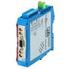
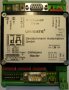
Changing or Replacing UNIGATE® CO(M)-ProfibusDP by UNIGATE® CM-PB
Zur Navigation springen
Zur Suche springen
The table below describes which points need to be observed when changing or replacing UNIGATE® CO(M) - ProfibusDP by UNIGATE® CM-PB.
| UNIGATE® CO(M) - ProfibusDP | UNIGATE® CM-PB | Note | |||||
|---|---|---|---|---|---|---|---|
| UNIGATE® CM-PB: UNIGATE® CM-PB ist available in housing colour Blue. Attention: OEM-devices may vary in colour. | |||||||
| Protocol | UNIGATE® CM-PB: Universalscript Deutschmann CM is loaded by state of delivery. This contains beside the CANopen mapping, which is also available in UNIGATE® CO(M) - ProfibusDP also further protocols. By configuration software WINGATE can be selected the needed protocol and UNIGATE® CM-PB maybe configured and used as UNIGATE® CO(M) - ProfibusDP. | ||||||
| Script | |||||||
| Software | |||||||
| configuration software WINGATE | UNIGATE® CM-PB: The configuration file (*.gwc) of UNIGATE® CO(M) - ProfibusDP can not be loaded in UNIGATE® CM-PB. | ||||||
| Mechanics | |||||||
| Housing WxHxD | 90 x 127 x 55 mm | 23 x 117 x 117 mm | |||||
| Protection type | IP24 | IP20 | |||||
| Connection-Power Supply | Mounting Position | ||||||
| Frontal-Bottom | Bottom | ||||||
| Power Supply | screw-plug-connector 2 pol. | screw-plug-connector 4 pol. X2 | |||||
| +24V/DC | Pin 1 | Pin 1 | |||||
| 0V (GND) | Pin 2 | Pin 2 | |||||
| Housing-Earthing | Earthing Clamp via DIN-Rail | Earthing Clamp via DIN-Rail | |||||
| UNIGATE® CO(M) - ProfibusDP: At elder devices the earthing is done by flat plug connectors or there is no earthing at the device. | |||||||
| Connection Serial | Mounting Position | ||||||
| Side Part - right | Top | Bottom | |||||
| Application Interface (RS232) | Screw-Plug Connector 3 pol. | Screw-Plug-Connector 3 pol. X1 | |||||
| Rx | Pin 1 | Pin 1 | |||||
| Tx | Pin 2 | Pin 2 | |||||
| AP-GND | Pin 3 | Pin 3 | |||||
| Application Interface (RS485) | Screw-Plug-Connector 4 pol. X1 | ||||||
| RS485 (+) | connect Pin 4 with Pin 6 | ||||||
| RS485 (-) | connect Pin 5 with Pin 7 | ||||||
| Application Interface (RS422) | Screw-Plug-Connector 4 pol. X1 | ||||||
| Rx422 (+) | Pin 4 | ||||||
| Rx422 (-) | Pin 5 | ||||||
| Tx422 (+) | Pin 6 | ||||||
| Tx422 (-) | Pin 7 | ||||||
| Debug-Interface | Screw-Plug-Connector 4 pol. X2 | ||||||
| Rx-Debug | Pin 3 | ||||||
| Tx-Debug | Pin 4 | ||||||
| Selection Application Interface | Not selectable | Not selectable/configurable | |||||
| RS232 | UNIGATE® CM-PB: In connection with Universalscript Deutschmann CM is only Application Interface RS232 available. | ||||||
| RS485 | |||||||
| RS422 | |||||||
| Termination | |||||||
| RS422 (Tx) | Connectible by slide switch below X1 | UNIGATE® CM-PB: Below X1 are to be found 2 slide switches for termination. | |||||
| RS422 (Rx) | Connectible by slide switch below X1 | ||||||
| RS485 | Connectible by one slide switch below X1 | UNIGATE® CM-PB: Only slide switch Tx422 has to be set to position ON. Slide switch Rx422 has to be set to position OFF. | |||||
| Application- Interface Rotary Coding Switches & LEDs | Mounting Position | Application- Interface Rotary Coding Switches & LEDs | |||||
| Frontal-Bottom | Frontal | ||||||
| Rotary Coding Switch S4 | Rotary Coding Switch S4 | UNIGATE® CM-PB: Operating modes may be selected correspondingly as at UNIGATE® CO(M) - ProfibusDP. Attention: Switch position "DD" is reserved for internal use and is not allowed to use. | |||||
| Rotary Coding Switch S5 | Rotary Coding Switch S5 | ||||||
| LED Power | LED Power | ||||||
| LED State | LED State | ||||||
| LED Error No / Select ID | LEDs 1/2/4/8 (Error No / Select ID) | ||||||
| Connection Fieldbus | Mounting Position | ||||||
| Frontal-Top | Frontal-Bottom | Frontal | Top | ||||
| CANopen | |||||||
| PROFIBUS | |||||||
| Termination | Connectible by slide switch | Connectible by slide switch | |||||
| Fieldbus Rotary Coding Switches & LEDs | Mounting Position | Fieldbus Rotary Coding Switches/Dip-switch/LEDs | |||||
| Frontal-Top | Frontal Bottom | Frontal | Top | ||||
| CANopen | CANopen | ||||||
| Dip-Switch | Dip-Switch | ||||||
| LED BUS Power | LED Power/State | ||||||
| LED BUS State | |||||||
| PROFIBUS | PROFIBUS | ||||||
| Rotary Coding Switch High | Rotary Coding Switch High | ||||||
| Rotary Coding Switch LOW | Rotary Coding Switch LOW | ||||||
| LED BUS Power | LED BUS Power | ||||||
| LED BUS Error | LED BUS | ||||||
| LED BUS State | LED BUS State | ||||||
| Device Description Files | |||||||
| CANopen | UNIGATE® CM-PB: An EDS - file can be generated by configuration software WINGATE. | ||||||
| PROFIBUS DPV0 | DAGW2862.gsd | DAGW2862.gsd | UNIGATE® CM-PB: The Ident Number may be set to "2862" via configuraton software WINGATE. With this setting the old GSD-file can be kept and the project needs not to be changed. | ||||
| PROFIBUS DPV1 | UGIC3218.gsd | ||||||
![]() = available
= available
![]() = not available
= not available
Further detailed information may be found in the corresponding manual in chapter "Technical Data".


